

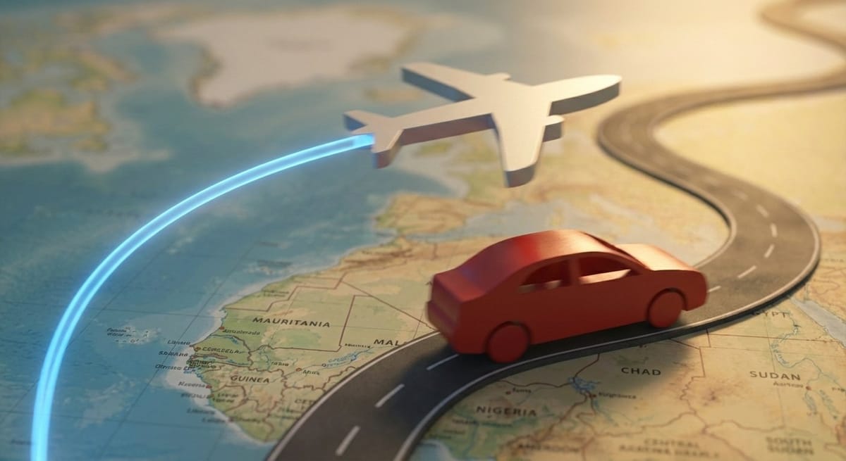
This tutorial walks through a production-grade workflow in DaVinci Resolve’s Fusion page, showing how to build a reusable 3D map animation system with camera rigs, animated routes, vehicle followers, and cinematic polish.
This tutorial outlines how to create a cinematic, documentary-style map animations in DaVinci Resolve’s Fusion page. We will create a sample animation that contains all the most common types of map animation effects.
Example Animation (coming soon):
- Follow an airplane flight from Chicago to Spain, highlighting the country borders.
- Zoom into Madrid.
- Animate a vehicle traveling through multiple Spanish cities, with labeled stops and cinematic camera moves.
Conceptual Overview
3D Workflow
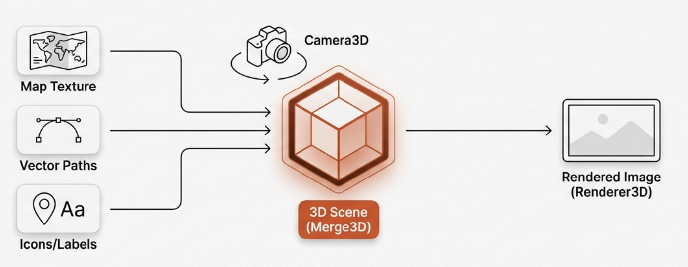
Map animations in Fusion rely on true 3D workflows:
- Map Texture: High-resolution texture placed on a 3D plane.
- Vector Paths: Vector-driven lines showing routes or borders.
- Icons & Labels: Either baked into the map or placed on independent 3D planes.
- Camera: Moves through 3D space for cinematic zooms and pans.
- Renderer3D: Converts the 3D scene back to a 2D image.
Why Use Fusion?
- True 3D camera movement.
- Resolution-independent vector animation.
- Cinematic effects: depth of field, motion blur, glow.
Phase 1: Asset Preparation
Sources
- Historical/Artistic Maps: https://rumsey.mapranksearch.com/
David Rumsey Historical Map Collection as a premier resource for high-quality historical and artistic maps that avoid the "standard" look of modern map plugins. Check out the 1911 world map in 12K resolution. - Modern/Satellite Maps: General modern maps are also frequently sourced directly from Google Images or via screenshots of Google Maps. Artistic maps can also be generated by AI.
- True 3D Terrain: https://heightmap.skydark.pl/
Created to serve maps for a video game called City Skylines. Export perfectly matched satellite images and their corresponding grayscale height maps for creating genuine 3D landscapes.- Use Auto map settings when creating map
- Download Map Image (menu icon) for graphic of the map style you have selected. DaVinci Resolve may require the image be converted to .TIFF or EXR. These formats are preferred over .jpg which can introduce compression artifacts (blocking) that become very visible during deep 16K zooms.
- Download height map png file
- Vector Maps: https://vemaps.com/
- Vector Assets: https://freevectormaps.com/
For political borders or regional highlights, animators often source EPS or SVG files from sites like Free Vector Maps - Icons: Car or plane PNG with transparent background. https://www.freepik.com/ or https://pngtree.com/
Tip: Always check licensing for commercial use.
Asset Strategy
Always plan resolution and overlay strategy before animation begins.
- Before starting, determine how far you intend to zoom.
- Continental flyovers: 8K resolution map image recommended
- Country → city zooms: 12–16K resolution recommended
- All elements must share the same map projection. Mixing projections (Mercator, satellite, artistic) leads to alignment errors where the path of a vehicle or a highlighted region appears distorted or misplaced relative to the visual landmarks on the underlying map image. To ensure a perfect fit, generate SVG borders from the same source map you are using for your background
- Match overlay resolution to the map. All background nodes used for paths or highlights must match the resolution of the base map, not the timeline.
- For low-resolution maps, use Super Scale: In the Media Pool, right-click the clip and set
Clip Attributes → Super Scale → 4x Enhancedto simulate a higher-resolution asset.
Phase 2: Core 3D Scene Setup
Project Settings
- Timeline: 30 fps
- Image Scaling: Center crop, no resizing
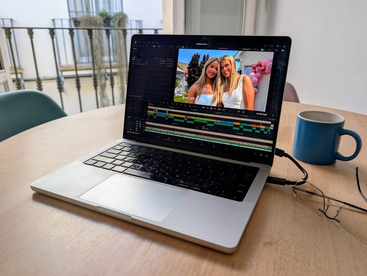
Fusion
In Effects tab, search for Fusion Composition and drag it into your timeline and make it 6-8-10–15 seconds long. Click on the composition to go to the Fusion tab.
Drag the map from the Media Pool onto the Fusion work area. This will create a MediaIn node. Select the node and use CTRL+Space to open search window to add additional nodes.
2D Map
You only need 6 nodes and here is how to set them up. Always name nodes clearly e.g., MAP_Plane, ROUTE_Path, CAR_Icon.
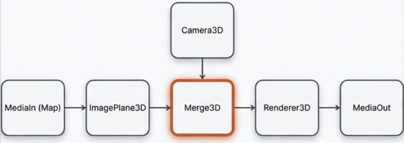
- Put the flat map image into 3D Space:
MediaIn (Map) → Crop (optional) → ColorCorrector (optional) → ImagePlane3D - Combines all 3D elements:
Camera3D → Merge3D
ImagePlane3D (Vehicle/Icon) → Merge3D - Outputs the final 2D image:
Merge3D → Renderer3D → MediaOut
Initial Setup
- Place the merge3D in the left viewer and the renderer in the right one by dragging the nodes into the viewer area or selecting node and keyboard 1 or 2.
- Camera3D: Move back along Z-axis by dragging the blue arrow in the viewer area until the map is visible in the viewer.
- Renderer3D:
- Set ‘Renderer Type’ from Software to Hardware Renderer for smooth playback.
- Un-check High Quality Preview during layout.
- Motion blur and accumulation effects should be disabled until final render.
- Crop: 'Keep Centered' checked
- ImagePlane3D: Scale 4–5 for smoother camera navigation.
- Save your project.
3D Terrain Map
- Import satellite + height map into media pool and bring them into the Fusion workspace.
- Create nodes: ImagePlane3D --> Displace3D --> Transform3D
- Attach map image to the ImagePlane3D node
- Attach height map to the Displace3D node
- Create nodes: 3DCamera --> Transform3D – > Transform3D --> Merge3D (with Transform3D node above)
- View Merge3D node in viewer.
- Adjust ImagePlane3D
- Increase Subdivisions to 500–1000. Work with it at 500 and consider cranking it up to 1000 for additional detail for final render.
- Set the Scale (10?)
- Disable high subdivisions and accumulation effects during layout; enable for final render.
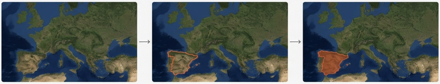
Phase 3: Highlighting Areas with SVG Borders
- Import SVG:
Fusion → Import → SVGand select your border file. Fusion converts it into Polygon mask nodes. - Styling: Within the imported SVG group, use the Background node to set the highlight color (e.g., a semi-transparent red or green).
- Alignment: Merge this group with your map. Use a Transform or Merge node to resize and position the SVG until it perfectly overlays Spain on the base map.
- Animate: Select the Outline node within the SVG group and keyframe the border width and Length parameter from 0 to 1 over the first 2 seconds to "draw" the border highlight.
Phase 4: Route Path Creation
Tools
- Polygon Node: lean, precise routes. Animation is controlled via the ‘length’ parameter
- Paint Node (Polyline Stroke): For stylized dotted lines. Set spacing for dotted line. Animation is controlled via the ‘write-on’ parameters.
- Path3D nodes simplify vehicle/icon integration along curves.
Creating the Route
- Drag in a Polygon node and a Background node to the work area. Pipe the Polygon into the Mask Input (top) of the Background.
- Drag the Background output over the Map output to automatically create a merge just before the ImagePlane3D.
- For 3D terrain, paths should be merged onto the map texture before the
Displace3Dnode so the path "hugs" the topography.
- For 3D terrain, paths should be merged onto the map texture before the
- Set the Background node providing the color for the path's resolution to "Image" (uncheck "Use Frame Format") to match the MediaIn map resolution (ie, 12k by 8k)
- On the Polygon node, it says "right click here for shape animation". Right click and select the remove polygonpolyline option.
- Select the Polygon node and draw the path on the map with the tool. Increase the Border Width and thickness of the Polygon line.
- Line color is set on the Background node.
- Add a Glow node between the Background and Merge nodes to make the line stand out more.
- In the Merge node, set the "Apply Mode" to "Overlay" or "Soft Light" for a subtle look, or keep it "Normal" but reduce the "Gain" in a ColorCorrector node for a "printed on" look.
Plot & Animate
- Animate the Polygon's length value with keyframes. If using Paint, set the
Write-On0 → 1. - Smooth motion with keyboard "s" to edit path in Spline Editor.
- Open Spline Tab in upper right
- Open Polygon and click the fit to zoom to see it better.
- Highlight all the keyframes and click "s"
- Ctrl+T to open EaseIn and EaseOut fields
- Ease In: 45
- Ease Out: 35
Phase 5: Vehicle or Plane Following the Route
Polygon Node
- Import PNG into ImagePlane3D (Z ~0.0001).
Pro-Tip: If your plane or car "flickers" as it moves, it is "Z-fighting" with the map. Increase the Z-translation of the icon slightly (0.002) until the flickering stops.
- Connect Transform3D to the path:
Publish Shape AnimationorConnect To Path3D. - Animate Displacement 0 → 1 to move the icon along the route.
- Connect Angle to Path Heading, enable Auto-Orient.
Paint Node
- Copy the Paint node and connect it just after the existing line's Paint node.
- Change the color so you can see what is happening
- Update first keyframe
- Set the WriteOn - End value to 0.001
- Set spacing to 0
- Update last keyframe WriteOn - Start value to 0.999
- Set Brush Controls to pre-existing icon or Clip to upload image.
- Set "Apply Mode" to merge (M icon)
Phase 6: Camera Animation
Create A Custom Camera Control Tool (Optional)
Control the camera with slider-driven animation by creating a custom camera control tool.
- Select the Camera node and add a transform3d after it, before the merge node.
- Add a Custom Tool node in a convenient spot.
- This will be our Camera Controller where we set our key frames.
- In Custom Tool -> config, rename the first 7 Number Controls to X, Y, Z, Pitch, Orbit, Tilt, Focus and deselect the rest.
- Pin the custom tool on the inspector by clicking on the pin icon on the custom tool inspector.
- Select the Camera to open it in the inspector with the custom tool.
- In the Camera's Transform tab, insert an "=" for the Translation's Z value and click enter. This makes the z-value into an expression.
- Drag the "+" label of the Z expression to the Custom Tool Z to connect them.
- Add "*2" to the formula to increase the sensitivity of the control.
- Camera's Control tab Focal Plane, enter "=" and enter to turn it into an expression.
- Connect this value to the focus value in Custom tool.
- Add "*2" to the formula.
- Select Transform3D and turn Translation - X, Y, and rotation - X, Y, Z rotation into expressions.
- Connect Translation X and Y to X and Y in our Custom Tool.
- Add "*5" to the 2 Translation formulas.
- Connect Rotation X to Pitch, Y to Tilt, and Z to Orbit.
- Add "*40" to the 3 Rotation formulas.
- For the Focus control, select Renderer
- Check "Enable Accumulation Effects"
- Reduce the Amount of Blur way down so that when you pull focus in the Custom Tool it is not too strong.
- To turn on Autofocus on the center, enter "=" in the Custom Control - Focus field to turn it into an expression. Use the "+" to connect it to the "Z" custom control.
- The "Target" feature in the
Camera3D(under the "Transform" tab). Setting the camera to "Track" a specific 3D crosshair makes cinematic orbits around a city much easier than manual rotation.
- In the Camera's Transform tab, insert an "=" for the Translation's Z value and click enter. This makes the z-value into an expression.
Set up Direct Camera Control (Optional)
If not using the Custom Camera control you can adjust the camera in the viewer to update values as well.
- In the Camera3D node Transform tab, right click on translate and select "Animate Translate Group" from the select list.
- Do the same for Rotation.
- Red diamonds will appear on the right side of the Translation and Rotation values to set the keyframe for the camera position
Keyframe Animation
- Animate keyframes using the Custom Tool sliders or the Camera in the viewer to update the camera Translate and Rotate values.
- After selecting all keyframes and hitting "s" on the keyboard to smooth the motion curves in the Spline Editor
Phase 7: Narrative Layers (Stops & Labels)
Overlay Methods:
- 2D Merge: Fast, baked into map. Pixelates during deep zooms.
- Independent 3D Planes: Maintains perfect sharpness, requires Z-depth management.
Point Circles:
- Use Ellipse or Paint node --> Background node --> merge
- Drag Ellipse to resize and place on map
- Color-code (red = start, green = end).
- Animate scale/bounce; synchronize with route Write-On.
- Keyframes
- Keyframe 1 set Border width small until point goes away.
- Forward 4 frames and set Border width to just above 0.0004
- Forward 3 frames and set Border width to -0.00004
- Forward 2 frames and set Border width to 0
- Open Spline tool
- Highlight all keyframes & "s"
- Keyframes
- Copy+Paste Ellipse and move before existing and -->
- Move to next destination
- Open Keyframes tab, highlight all and move keyframe
Labels:
- Text+ nodes, optionally masked to pop from behind circles.
- Apply Billboard constraint so text always faces the camera.
Phase 8: Cinematic Polish
Depth of Field
If not using the custom control, you can add a depth blur with either Accumulation Effects (broadcast quality) or a Depth Blur node (very fast).
If you see "bleeding" (where the blurred background leaks into the sharp foreground), stick with Accumulation Effects. This usually happens with very sharp, high-contrast 3D objects like airplane icons. For flat maps and terrain, Depth Blur is almost always the better choice.
- Depth Blur Node:
If not using the custom control, you can add a depth blur node for very fast depth blur. This technique can produce halos but is suitable for YouTube and quick turn-arounds.- Step 1: Prepare the Renderer
- Select your Renderer3D node.
- Go to the Output Channels tab in the Inspector.
- Check the box for Z (Depth). This tells Fusion to create a "hidden" grayscale map where white is close to the camera and black is far away.
- Important: Turn off "Accumulation Effects" in the Renderer3D settings to save speed.
- Step 2: Add the Depth Blur Node
- Place a Depth Blur node between your
Renderer3Dand theMediaOut. - In the Inspector, ensure the Z-Channel is set to "Z".
- Click the Pick button (crosshair icon) and click on the area of your map you want to be in focus in the viewer.
- Adjust the Blur Size to your liking.
- Place a Depth Blur node between your
- Step 1: Prepare the Renderer
- Accumulation Effects:
- In Render3D node
- Set Render Type to "openGL Renderer"
- Enable Accumulation Effects: checked
- Depth of Field: checked
- Quality: 4
- Amount of Blur: 0.02
- Camera3D node
- Controls - Control Visibility - Focal Plane: checked
- Controls - Control Visibility - Sub Divisions: 3
- In Viewer, a green rectangle representing the focal plane will appear.
- Right-click viewport and change it to "top" so you can see where the image and focal planes.
- There is a glitch in DaVinci that doesn't show you the image plane on the focal plane when you go to the top view. To fix it, show the background in the viewport 1 and then change it to Merge3D to see both.
- Set keyframes in Camera3D Node's focal plane setting. Every 30 frames (1 second) set a new keyframe by adjusting the green focal plane in the viewer and clicking the keyframe diamond.
- In Render3D node
Atmospheric Haze
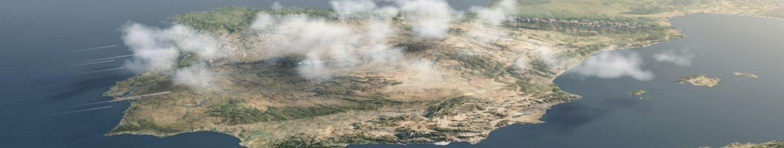
Adding atmospheric layers can turn a flat digital map into a cinematic documentary shot. It provides scale showing how high the camera is and parallax clouds moving faster than the ground.
The "Cloud" Node Flow: Fast Noise (Clouds) → ImagePlane3D (Offset in Z-space) → Merge3D (Combined with Map & Camera)
- The "Atmospheric Haze" (Simple 2D Method)
As the camera zooms out to a continental view, the edges of the earth should look slightly blue and foggy. This simulates the "thick" air near the horizon without slowing down your render.- The Setup: Add a Fast Noise node.
- The Look: In the Inspector, set Detail to 0 and Contrast to 0.5. Change the color to a very pale sky blue or light gray.
- The Mask: Connect a Merge node between your
Renderer3DandMediaOut. Plug the Fast Noise into the Foreground. - The Blend: Add an Ellipse Mask to the Fast Noise. Soften the edges significantly (Soft Edge slider) and invert it so the "haze" only lives at the corners and horizon of your frame.
- Procedural 3D Clouds (The Professional Way)
For a realistic flyover, you want clouds that hover above the map so they move independently of the ground.- Step A: Create the Cloud Texture:
- Add a Fast Noise node.
- In the Inspector (under the "Noise" tab):Increase Detail to 3.0–5.0 for "wispy" edges.Increase Scale so the clouds look like large banks, not tiny dots.Increase Seethe Rate slightly (0.01). This makes the clouds "boil" and change shape slowly over time.
- In the "Color" tab, set Color 1 to White and Color 2 to transparent (Alpha = 0).
- Step B: Place Clouds in 3D Space
- Connect the Fast Noise output to a new ImagePlane3D.
- Connect this new ImagePlane3D into your main Merge3D.
- Crucial Step: In the 3D viewer, use the green arrow to lift the Cloud Plane slightly above the Map Plane on the Y or Z axis (depending on your orientation).
- Transparency: In the
ImagePlane3D(Material tab), ensure the "Blending Mode" is set to Alpha or Additive so you can see the map through the gaps in the clouds.
- Step A: Create the Cloud Texture:
- Adding "Aerial Perspective" (Depth Haze)
In the real world, objects further from the camera look less contrasty and more blue.- Add a Fog node (search
Fog) between yourMerge3DandRenderer3D. - This tool allows you to set a "start" and "end" distance for fog.
- As your camera tilts to look at the horizon, the distant mountains will naturally fade into a soft haze, while the ground directly under the camera remains sharp.
- Add a Fog node (search
- Cinematic Lighting for Clouds
To make the clouds feel "integrated" rather than just a flat overlay:- Go to your DirectionalLight (from the Terrain phase).
- Position the light so it hits the clouds from the side.
- In the
Renderer3D, make sure Shadows are enabled. This will cast subtle, soft shadows from the clouds onto the map below, which is the ultimate hallmark of a high-budget documentary map.
Pro Tip: A common mistake is to make the clouds too bright. Real clouds from 30,000 feet often have a bit of transparency. Reduce the Gain on your Merge node to blend them in subtly.
Additional Effects
- Glow / Soft Glow: Make routes pop.
- Drop Shadow: Adds depth to routes and vehicle/icon.
- Add dropshadow node before merge node to set the dropshadow
- Motion Blur: Enable in Renderer3D. Be warned that it is intensive and will dramatically slow the render time.
- Can turn on Motion Blur on the line Polygon and set value to 8 or 9.
- DVE Node: Place node before output as an alternative way of tilting map canvas.
Phase 9: Performance & Render Workflow
- Use Proxy Mode during layout.
- Use Cache to Disk: Right-click the
Renderer3Dor finalMergenode > Cache to Disk. This pre-renders the heavy 3D math so the user can see the camera move in real-time. - Disable accumulation, motion blur, high subdivisions while editing.
- Final render:
- Enable High Quality Preview, Motion Blur, Accumulation Effects;
- confirm resolution.
- Set the Renderer3D ‘Renderer Type’ from Hardware Renderer to Software. Software Renderer is often more stable for the final high-resolution export if the GPU runs out of VRAM on 12K textures.
- Switch Renderer type if artifacts appear.
Final Notes
This workflow scales from YouTube videos to broadcast documentaries.
Common Failure Points
Here are the most common map animation issues and fixes:
- Blurry lines or labels → resolution mismatch between background node and map.
- SVG borders misaligned → scale or projection mismatch.
- Jittery camera motion → un-smoothed spline curves.
- Flickering overlays → Z-fighting when planes share the same depth.
- Slow playback → accumulation effects or high subdivisions enabled too early.

Comments ()